DIYables Relay 5V 1-Channel
 Click to zoom
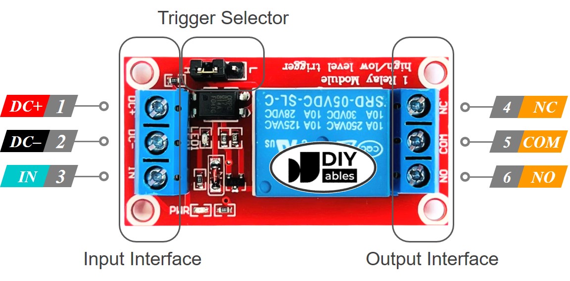
Quick Overview
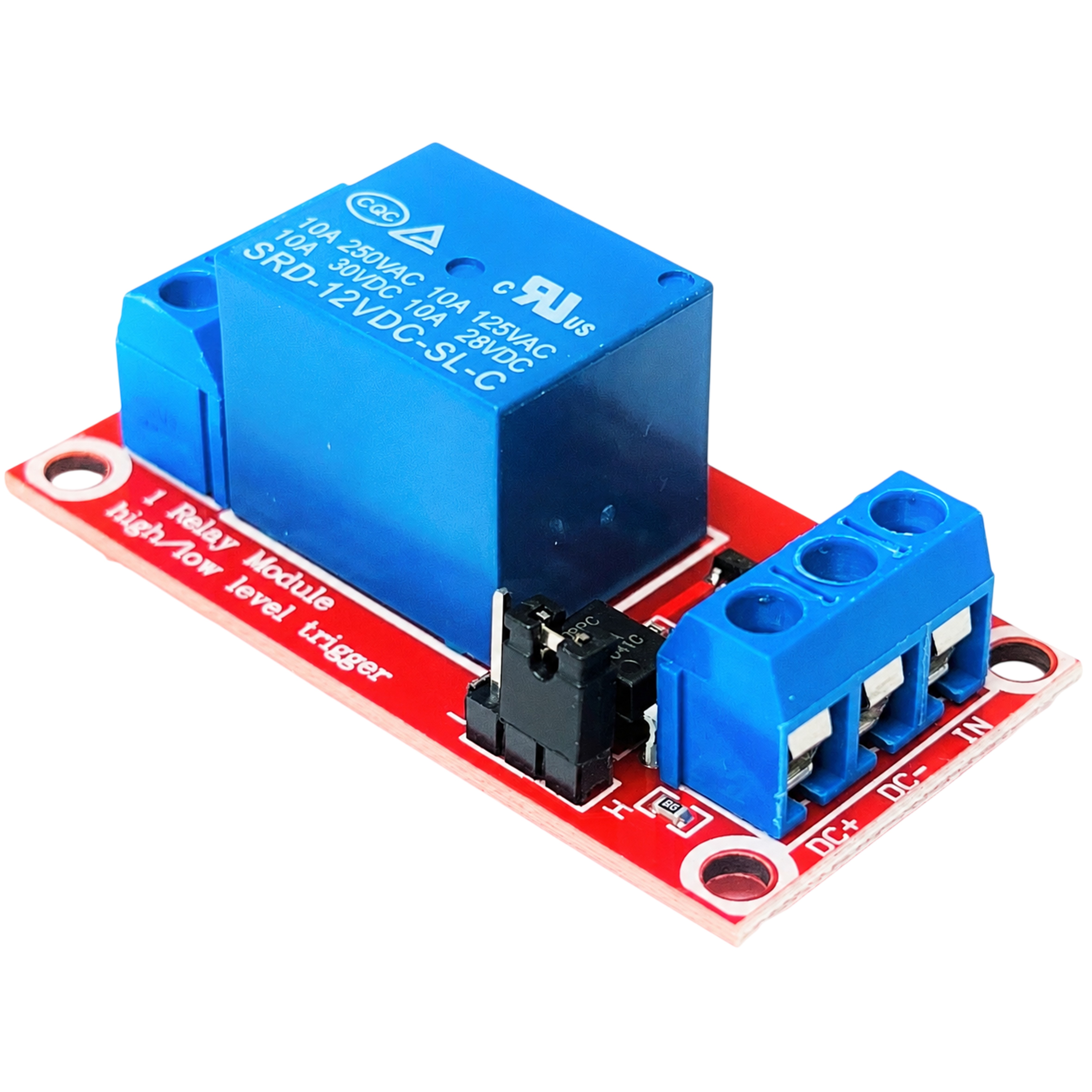
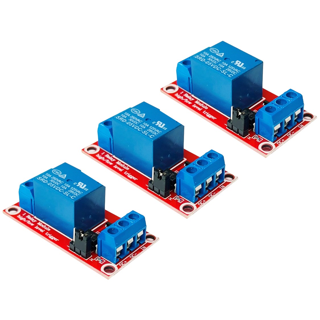
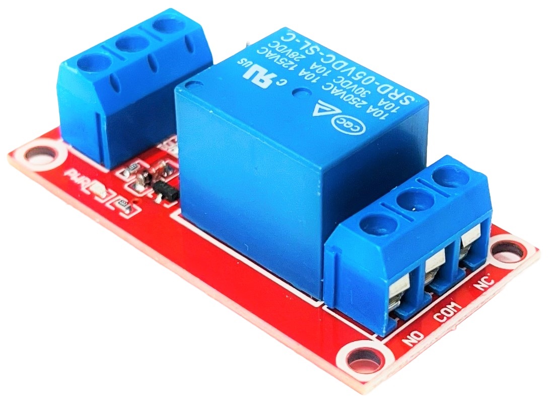
The DIYables 5V 1-channel relay module is a switching device that allows microcontrollers to control high-power AC or DC loads. Each module features optocoupler isolation for safe operation, terminal blocks for easy wiring, and both normally open (NO) and normally closed (NC) contacts.
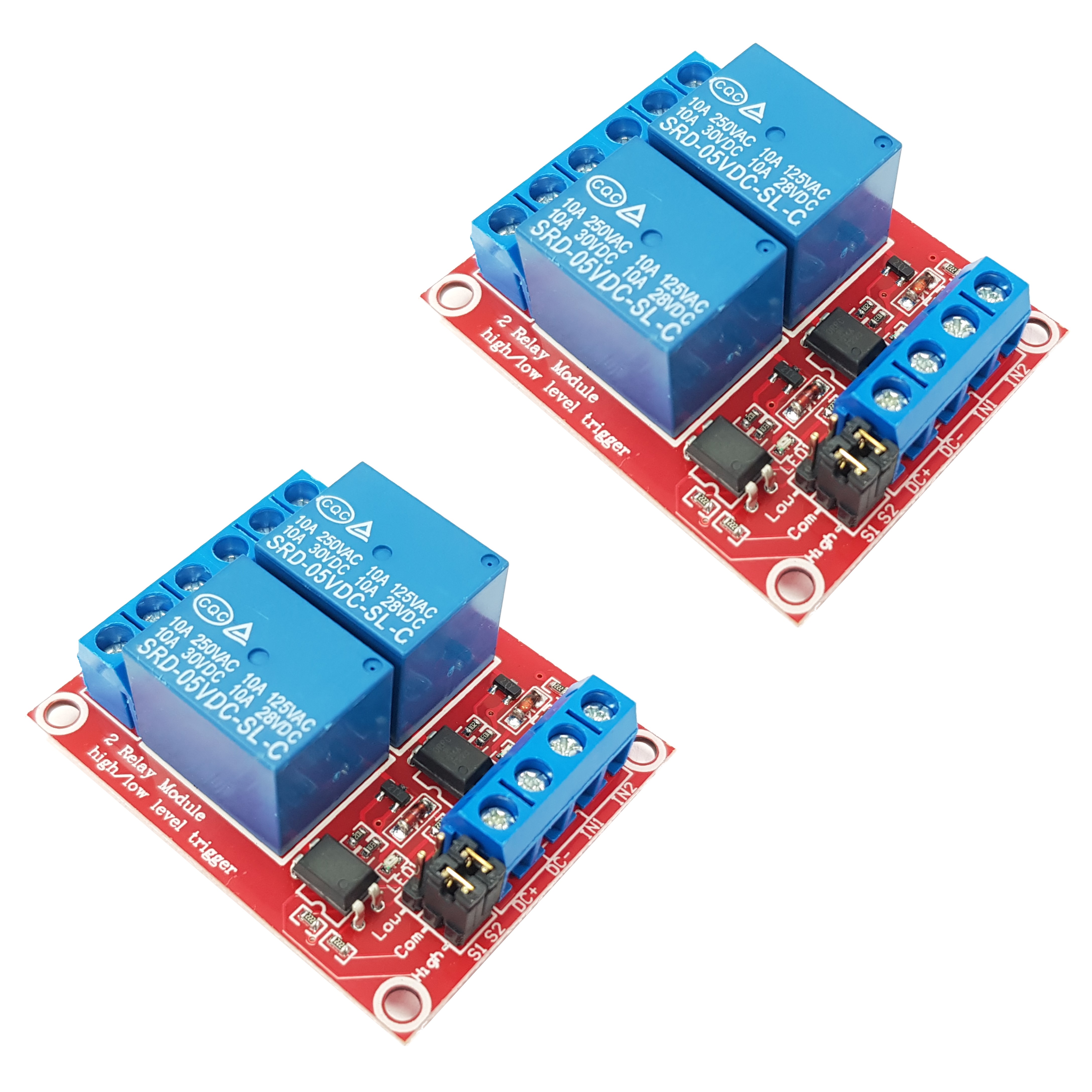
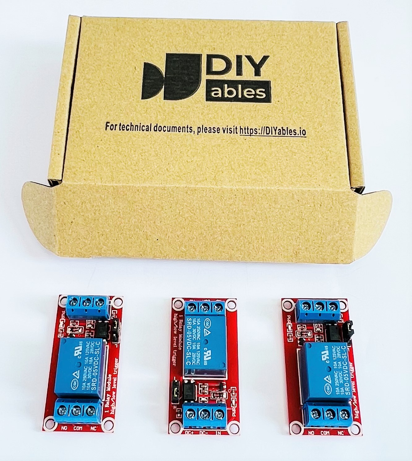
This 3-pack includes three relay modules with selectable high-level or low-level triggering via jumper. Two LED indicators show power status (green) and relay state (red). The modules work with Arduino, ESP32, ESP8266, Raspberry Pi, and any 3.3V-5V microcontroller for home automation, lighting control, and power switching applications.
Key Features
- Optocoupler Isolation — Safe isolation between control and load circuits
- High/Low Level Trigger — Selectable trigger mode via jumper (COM-L or COM-H)
- NO and NC Contacts — Both normally open and normally closed terminals available
- Terminal Blocks — Screw terminals for both input and output connections
- LED Indicators — Green power LED and red relay status LED
- Fault-Tolerant Design — Relay won't operate if control line is broken
- 3-Pack — Includes three relay modules
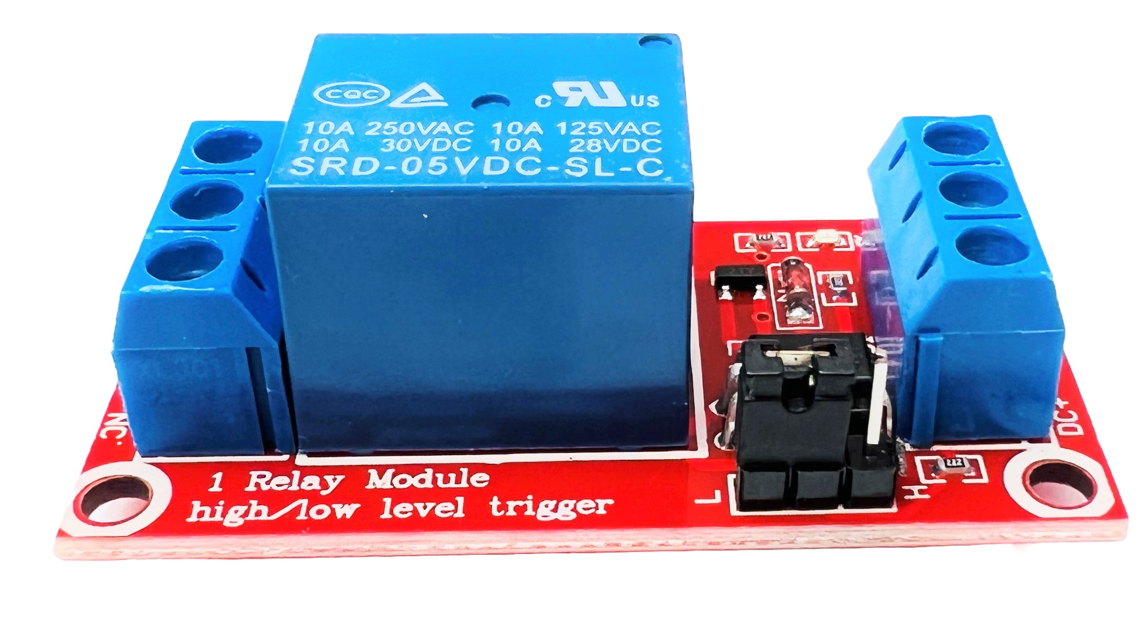
- High Load Capacity — AC 250V/10A, DC 30V/10A maximum load
- Presoldered and Not Soldered Options — Provided in presoldered and not soldered versions for selection
- Tutorial Support — Comprehensive tutorials for Arduino, ESP32, ESP8266, and Raspberry Pi
SPECIFICATION
| Specification | Value |
|---|---|
| Product Type | 1-Channel Relay Module |
| Operating Voltage | 5V DC |
| Trigger Voltage | 3.3V - 5V |
| Trigger Current | 5mA |
| Trigger Mode | High-level or Low-level (selectable via jumper) |
| Maximum Load | AC 250V/10A, DC 30V/10A |
| Isolation | Optocoupler isolation |
| Indicators | Power LED (green), Relay status LED (red) |
| Contacts | NO (Normally Open), NC (Normally Closed), COM (Common) |
| Dimensions | 50mm x 26mm x 18.5mm (L x W x H) |
| Package Quantity | 3 pieces |
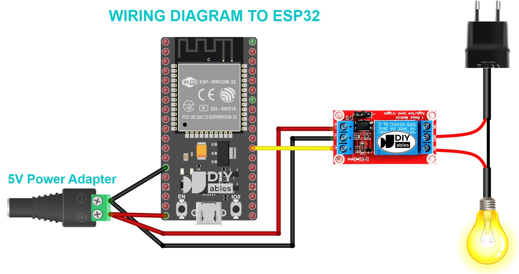
INTERFACE
INPUT INTERFACE
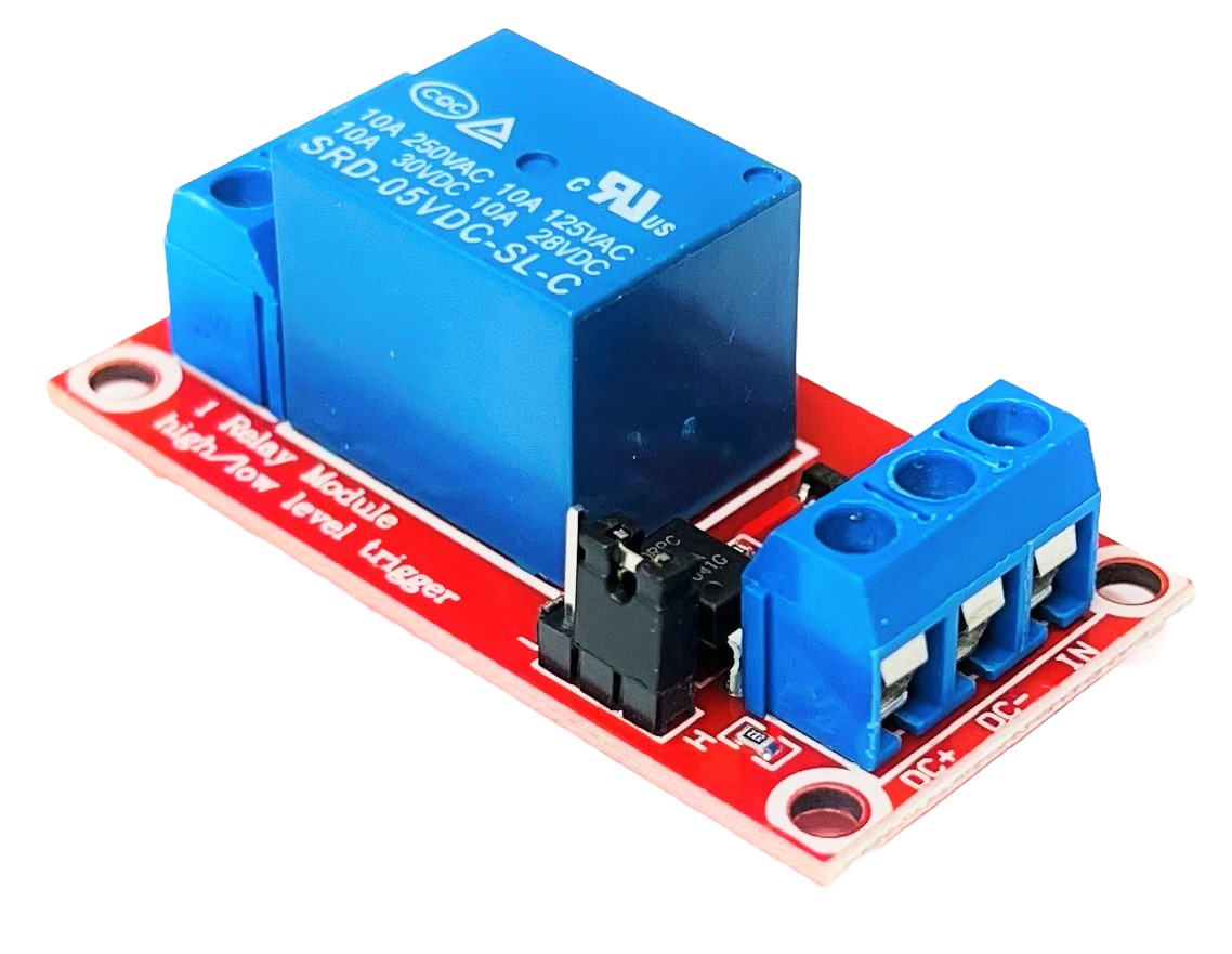
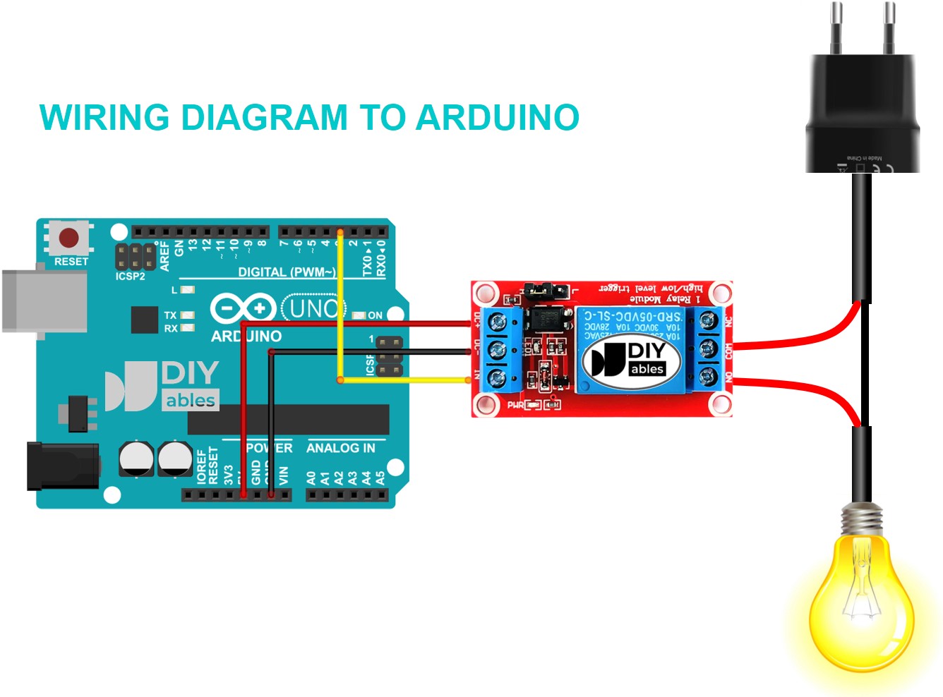
- DC+ : Connect the positive pole of the 5V power supply.
- DC- : Connected the negative pole of the 5V power supply.
- IN: Signal trigger input (3.3V to 5V, high or low level signal selected via a jumper).
OUTPUT INTERFACE
- NO: The normally open interface.
- NC: The normally closed interface.
- COM: The common interface for both normally open and normally closed.
HIGH/LOW LEVEL TRIGGER SELECTION JUMPER:
- If the jumper is placed between COM and L, the relay uses LOW level trigger.
- If the jumper is placed between COM and H, the relay uses HIGH level trigger.
HOW IT WORKS
High Level Trigger:
- When IN is LOW level signal, the NO does not connect with COM and the NC connects with COM.
- When IN is HIGH level signal, the NO connects with COM and the NC does not connect with COM.
Low Level Trigger:
- When IN is LOW level signal, the NO connects with COM and the NC does not connect with COM.
- When IN is HIGH level signal, the NO does not connect with COM and the NC connects with COM.
Tutorials
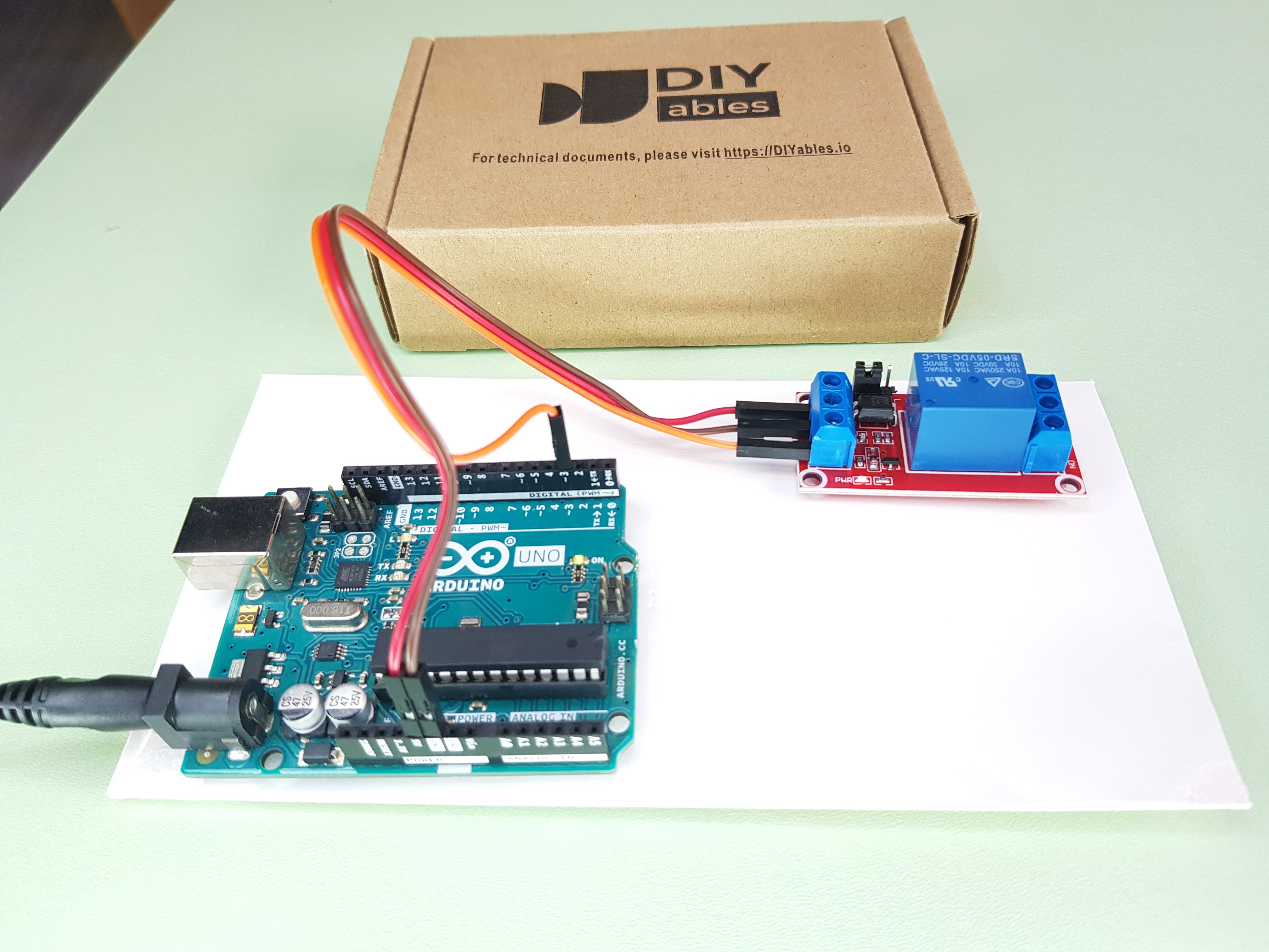
COMPATIBLE HARDWARE
- Arduino boards (UNO, Mega, Nano, etc.)
- ESP32 development boards
- ESP8266 (NodeMCU, Wemos D1, etc.)
- Raspberry Pi (all models)
- Raspberry Pi Pico
- Any microcontroller with 3.3V-5V digital output