DIYables L298P Dual H-Bridge Motor Driver Shield for Arduino Uno R3/R4, Mega, Due, Giga, 4A Dual Channel Motor Control Module for DC and Stepper Motors
 Click to zoom
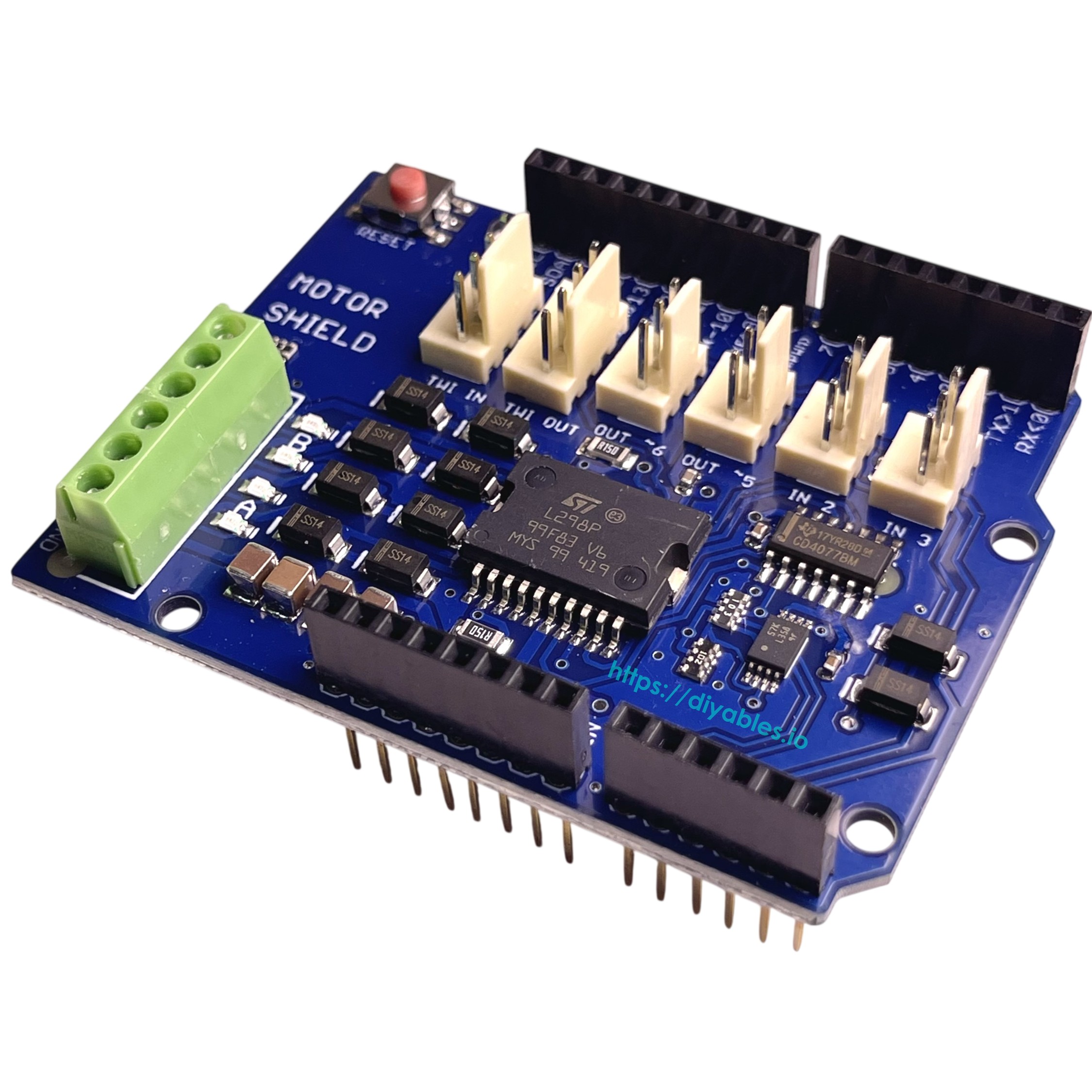
Quick Overview
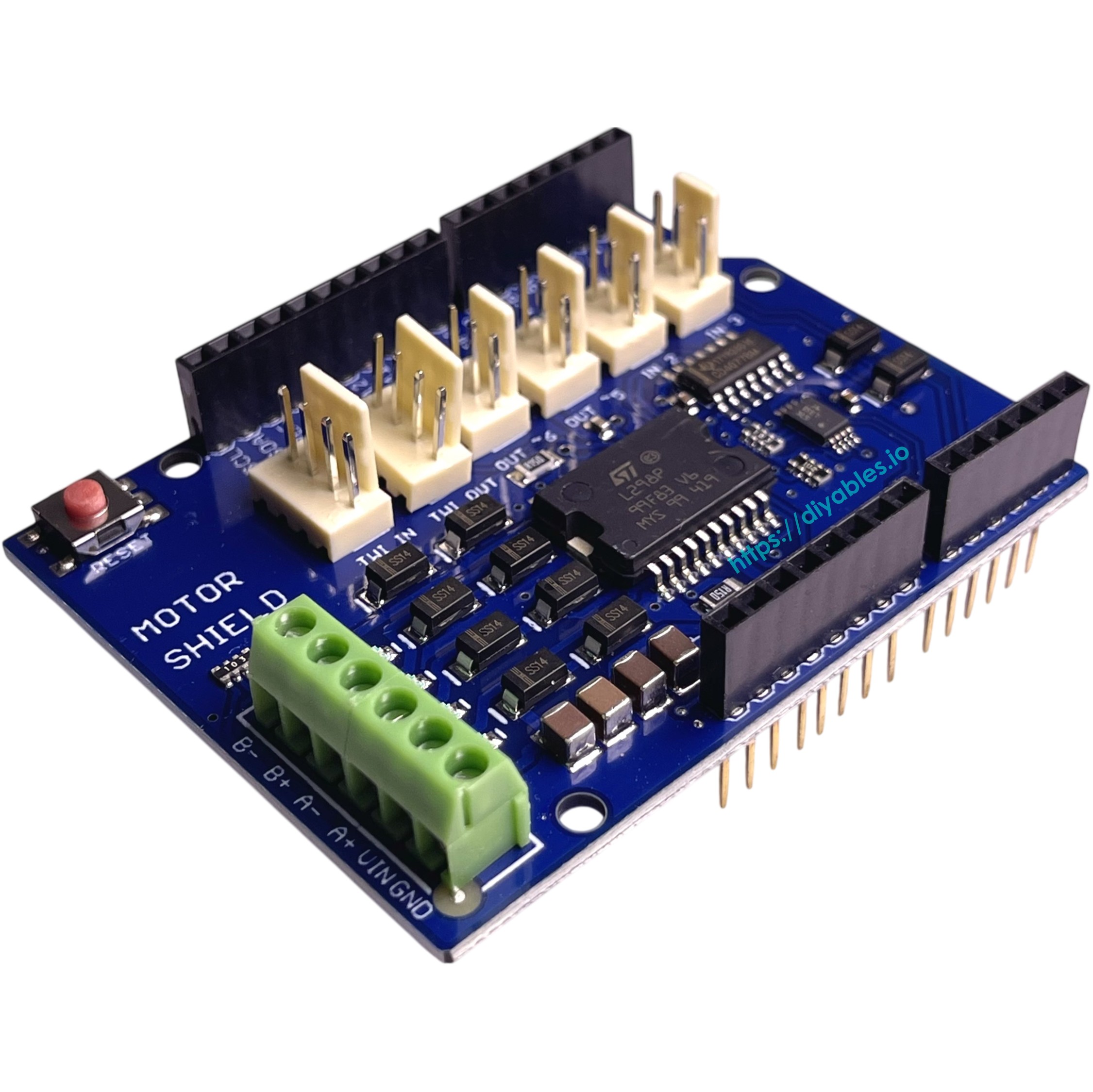
The DIYables L298P Dual H-Bridge Motor Driver Shield is a powerful and reliable motor control solution designed for Arduino Uno R3, R4, Mega, Due, and Giga boards. Featuring the L298P dual full-bridge motor driver chip, this shield enables precise control of DC motors, stepper motors, relays, solenoids, and other inductive loads, making it an essential component for robotics, automation, and motion control projects. With support for up to 4A total current output and independent dual-channel control, it delivers professional-grade performance in a compact Uno-compatible form factor.
This motor driver shield provides independent speed and direction control for two DC motors or one bipolar stepper motor simultaneously, with each channel supporting up to 2A continuous current with proper cooling. Built-in thermal shutdown and overcurrent protection features ensure safe and stable operation during extended runtime or high-load conditions. The shield's PWM-based speed control allows smooth and precise motor operation, while its Uno form factor design ensures compatibility with standard Arduino shields and rapid prototyping workflows.
Ideal for smart cars, robotic arms, mobile robots, CNC machines, and automated motion control systems. Perfect for educational projects, DIY robotics, industrial automation prototypes, and any application requiring reliable dual-motor control. Fully compatible with Arduino IDE and works seamlessly with Arduino Uno, Mega, Due, Giga, and other Uno-style development boards.
Key Features
- L298P Dual H-Bridge Driver — Uses the L298P dual full-bridge motor driver chip for controlling DC motors, stepper motors, relays, solenoids, and other inductive loads
- Independent Dual Channel Control — Enables precise speed and direction control of two DC motors or one stepper motor simultaneously
- High Current Output — Supports up to 2A continuous current per channel with proper cooling, 4A total output for driving higher-power motors
- Thermal Shutdown Protection — Built-in thermal protection prevents overheating damage during long runtime or high-load operation
- Overcurrent Protection — Integrated overcurrent protection ensures safe and stable operation under load-intensive conditions
- PWM Speed Control — Smooth and precise motor speed control using PWM signals from Arduino digital pins
- Bidirectional Motor Control — Full H-bridge design allows forward and reverse direction control for both channels
- Uno Form Factor Shield — Designed with Uno-compatible form factor that stacks directly onto Arduino Uno, R3, R4, Mega, Due, and Giga boards
- Arduino IDE Compatible — Fully compatible with Arduino IDE for rapid prototyping and easy programming
- Wide Compatibility — Works with Arduino Uno R3, R4, Mega, Due, Giga, and other Uno-style boards
- Tutorial Support — Comprehensive tutorials for Arduino motor control, robotics, and automation projects
- Versatile Applications — Perfect for smart cars, robotic arms, mobile robots, CNC machines, automated systems, and motion control projects
SPECIFICATION
| Specification | Value |
|---|---|
| Product Type | Dual H-Bridge Motor Driver Shield |
| Model/Chip | L298P dual full-bridge motor driver |
| Motor Channels | 2 independent channels |
| Maximum Current | 2A per channel (continuous with cooling), 4A total |
| Peak Current | Up to 3A per channel (short duration) |
| Operating Voltage | 6-12V DC (motor supply voltage) |
| Logic Voltage | 5V DC (from Arduino) |
| Control Interface | Digital PWM pins from Arduino |
| Speed Control | PWM (Pulse Width Modulation) |
| Direction Control | Digital I/O pins for H-bridge switching |
| Motor Types | DC motors, bipolar stepper motors, relays, solenoids |
| Protection Features | Thermal shutdown, overcurrent protection |
| Form Factor | Arduino Uno shield compatible |
| Mounting | Stacks directly onto Arduino Uno/R3/R4/Mega/Due/Giga |
| Dimensions | 68mm x 53mm (approx.) |
| Package Quantity | 1 piece |
| Compatibility | Arduino Uno R3, R4, Mega, Due, Giga, and Uno-style boards |
| Applications | Smart cars, robotic arms, mobile robots, CNC machines, automation, motion control systems |
PINOUT
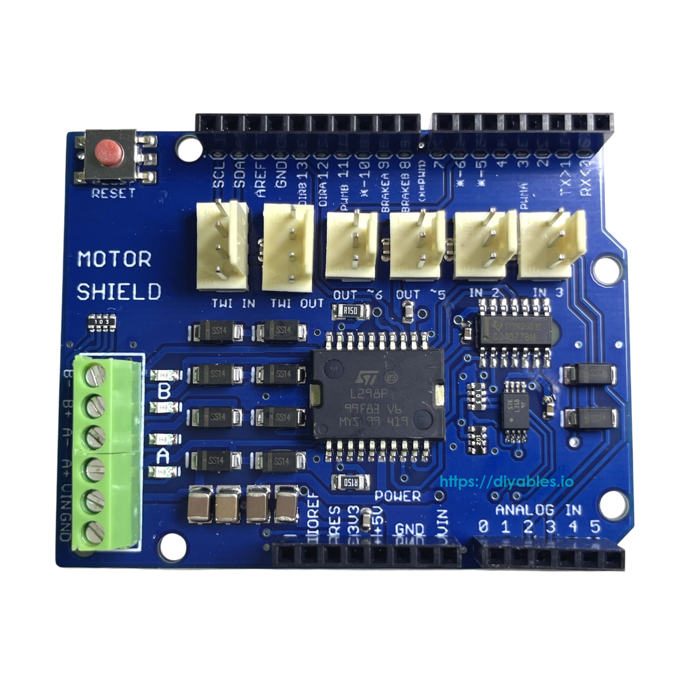
This shield has two separate channels, A and B, each using 4 Arduino pins to drive or sense the motor — 8 pins total. Each channel can independently drive a DC motor, or both channels can be combined to drive one bipolar stepper motor.
| Function | Channel A | Channel B |
|---|---|---|
| Direction | D12 | D13 |
| PWM | D3 | D11 |
| Brake | D9 | D8 |
| Current Sensing | A0 | A1 |
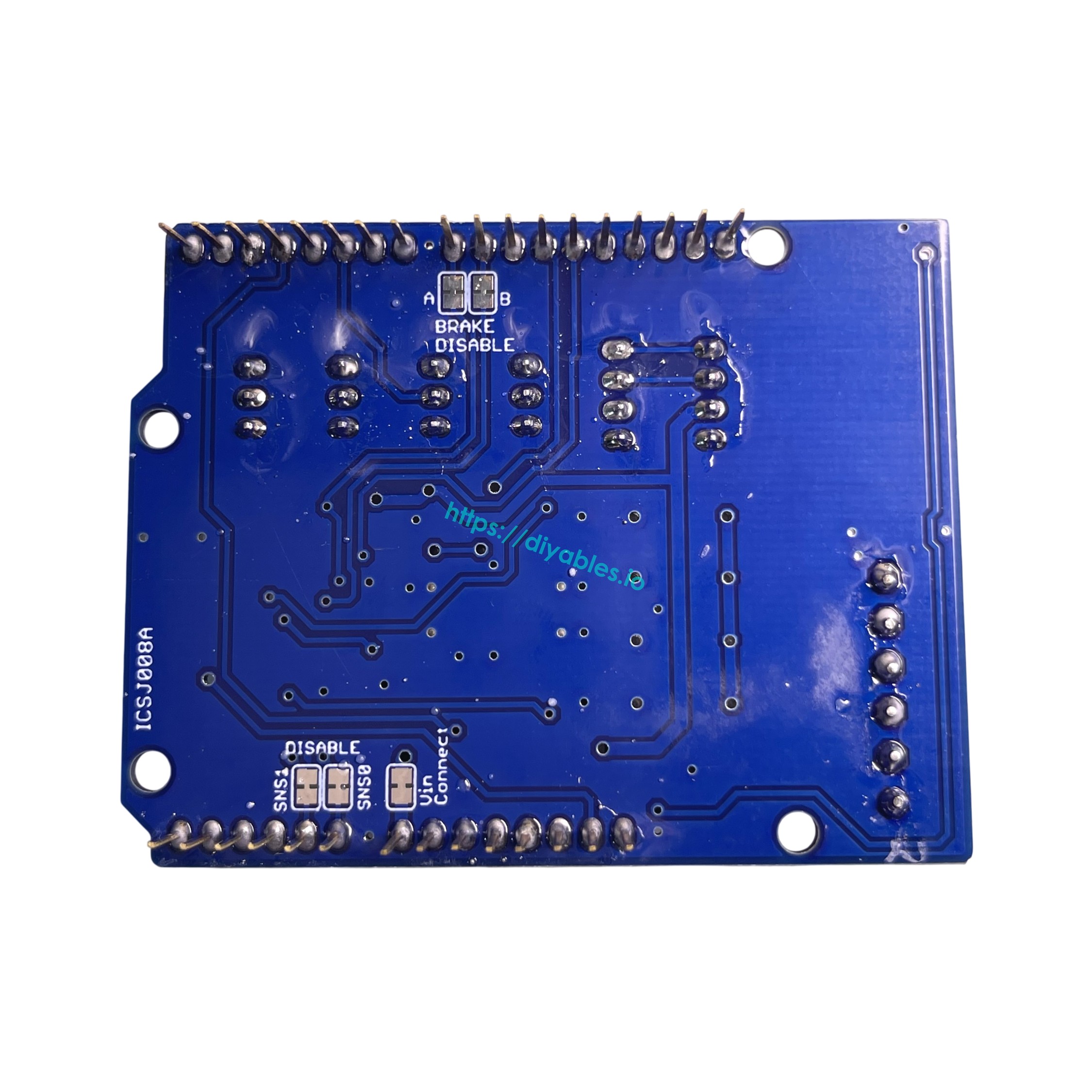
The Brake and Current Sensing features can be disabled by cutting the respective jumpers on the back of the shield, freeing those pins for other use.
The shield also includes the following additional connectors:
- Screw terminals for connecting motors and their power supply
- 2 TinkerKit connectors (3-pin) connected to A2 and A3 — not connected to the motor driver and free to use; labeled as analog inputs, but the pins can be used as input or output depending on the application
- 2 TinkerKit connectors (3-pin) connected to D5 and D6 — not connected to the motor driver and free to use; labeled as analog outputs, but the pins can be used as input or output depending on the application
- 2 TinkerKit connectors (4-pin) for the TWI (I2C) interface — not connected to the motor driver and free to use; labeled as input and output, but can be used in either direction depending on the application
DC Motor Connection: Connect the two wires of each DC motor to the (+) and (−) screw terminals for channels A and B. Control direction by setting DIR A/DIR B HIGH or LOW; control speed by varying the PWM A/PWM B duty cycle. Setting Brake A/Brake B HIGH actively brakes the motor instead of coasting. Current through each motor can be measured via A0 (channel A) and A1 (channel B) using analogRead() — the voltage is calibrated so that 3.3V corresponds to the maximum channel current of 2A.
Tutorials
COMPATIBLE HARDWARE
- Arduino Uno R3 — Stacks directly as shield
- Arduino Uno R4 WiFi/Minima — Full shield compatibility
- Arduino Mega 2560 — Compatible shield mounting
- Arduino Due — Works as motor driver shield
- Arduino Giga R1 WiFi — Compatible form factor
- Arduino Leonardo — Shield compatible
- Any Arduino Uno-style board — Compatible with Uno form factor shields
- DC motors (6-12V) — Two independent motors or one stepper
- Bipolar stepper motors — Single stepper motor control
- Robotic car chassis — Motor control for mobile robots
- Robotic arms — Multi-motor control systems
- CNC machines — Stepper motor control applications
POWER
The shield must be powered by an external supply — motor current often exceeds the USB current limit. The L298P chip has two separate internal power rails: one for logic (supplied by the Arduino) and one for the motors (supplied via the shield's Vin screw terminal).
Power-related screw terminal pins:
- Vin — Motor power input. By default (Vin Connect jumper intact), this also powers the Arduino board the shield is mounted on.
- GND — Ground.
A "Vin Connect" jumper on the back of the shield connects the shield's Vin screw terminal to the Arduino's Vin pin. Cutting this jumper fully isolates the two power rails.
WARNING
If the "Vin Connect" jumper is not cut, never power the shield's Vin screw terminal and the Arduino's barrel jack simultaneously. Both would drive the same Vin line from different supplies, which can damage the Arduino or the power supply.
Case 1: Motor supply is 6–7V
This voltage is too low for the Arduino's Vin pin (minimum 7V recommended). There are two options:
Option A — Arduino via USB, Vin Connect jumper cut (recommended):
- Cut the "Vin Connect" jumper on the back of the shield.
- Connect the 6–7V motor supply to the shield's Vin (+) and GND (−) screw terminals.
- Power the Arduino via USB cable.
Option B — Arduino via USB, Vin Connect jumper intact:
- Leave the "Vin Connect" jumper intact.
- Connect the 6–7V motor supply to the shield's Vin (+) and GND (−) screw terminals.
- Power the Arduino via USB cable. The Arduino will be powered by USB and the 6–7V on the Vin pin will be ignored by the Arduino's onboard regulator.
Option C — Arduino via barrel jack, Vin Connect jumper cut:
- Cut the "Vin Connect" jumper on the back of the shield.
- Connect the 6–7V motor supply to the shield's Vin (+) and GND (−) screw terminals.
- Connect a separate 7–12V supply to the Arduino's barrel jack.
※ NOTE THAT:
Option B works because the Arduino automatically uses USB power when present. However, cutting the jumper (Option A or C) is recommended to fully isolate the motor supply from the Arduino's Vin pin.
Case 2: Motor supply is 7–12V
This voltage range is safe for both the shield and the Arduino's barrel jack, giving you two options.
Option A — Single supply for both board and shield (Vin Connect jumper intact):
- Leave the "Vin Connect" jumper intact.
- Connect the 7–12V supply to the shield's Vin (+) and GND (−) screw terminals.
- The supply powers both the motors and the Arduino via the Vin pin. Do not also connect the Arduino's barrel jack.
> Note: You can still connect USB at the same time (e.g., for serial monitoring or programming). The Arduino will be powered by the external supply via Vin, not USB.
Option B — Separate supplies for board and shield (Vin Connect jumper cut):
- Cut the "Vin Connect" jumper on the back of the shield.
- Connect the 7–12V motor supply to the shield's Vin (+) and GND (−) screw terminals.
- Power the Arduino via USB cable, or connect a separate 7–12V supply to the Arduino's barrel jack.
Case 3: Motor supply is 12–18V
This voltage exceeds the Arduino's safe barrel jack input range (max 12V). You must cut the "Vin Connect" jumper to protect the Arduino.
Option A — Arduino via USB:
- Cut the "Vin Connect" jumper on the back of the shield.
- Connect the 12–18V motor supply to the shield's Vin (+) and GND (−) screw terminals.
- Power the Arduino via USB cable.
Option B — Arduino via barrel jack (separate supply):
- Cut the "Vin Connect" jumper on the back of the shield.
- Connect the 12–18V motor supply to the shield's Vin (+) and GND (−) screw terminals.
- Connect a separate 7–12V supply to the Arduino's barrel jack.
Power Summary
| Motor Supply | Vin Connect Jumper | Arduino Power | Notes |
|---|---|---|---|
| 6–7V | Cut (recommended) | USB | Fully isolates motor supply from Arduino |
| 6–7V | Intact | USB | Arduino ignores 6–7V on Vin; USB takes priority |
| 6–7V | Cut | Barrel jack (7–12V) | Separate supply for Arduino |
| 7–12V | Intact | No need, Auto from shield via Vin | One supply powers both motors and Arduino; do not use barrel jack |
| 7–12V | Cut | USB or barrel jack (7–12V) | Separate supplies for motor and Arduino |
| 12–18V | Cut (required) | USB | Must cut jumper to protect Arduino from high voltage |
| 12–18V | Cut (required) | Barrel jack (7–12V) | Must cut jumper; separate supply for Arduino |